If you’ve ever watched a pick and place robot seamlessly sorting tiny electronic components onto a circuit board, or stacking identical bottles into a shipping crate, you might be forgiven for assuming that all “seeing” systems for these machines are the same. As someone who’s spent the last decade designing, building, and refining pick and place robots for manufacturing and logistics clients, I can tell you that’s far from true. The vision system at the core of a pick and place robot isn’t just a camera—it’s a customized assembly of sensors, software, and processing hardware, tailored to the specific task the robot is meant to do. Too often, companies new to automation ask me: “Can’t we just attach a webcam to our robot?” The answer is almost always no. A pick and place robot’s vision system has to perform in environments that trip up regular cameras: low light, moving parts, glossy or transparent objects, and high-speed operations where even a millisecond of delay translates to costly errors. Pick and Place Robot
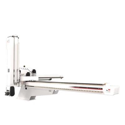
Let me break down the vision systems we most commonly integrate into our pick and place robots, and why each matters, starting with the most foundational: machine vision cameras. Unlike consumer webcams built for streaming or casual photography, machine vision cameras are calibrated for consistent, high-speed performance in industrial settings. They come in two primary types for pick and place applications: area-scan and line-scan cameras. Area-scan cameras capture a single 2D frame of a scene in an instant, making them ideal for detecting parts on a conveyor belt or a workbench—tasks where you need a full view of an object to identify its shape, color, or orientation. For example, when we build a robot to pick small plastic connectors for automotive wiring harnesses, an area-scan camera captures a 1-megapixel or 5-megapixel frame at 30 to 60 frames per second, enough to track connectors moving at 100 feet per minute along a line. Line-scan cameras, on the other hand, capture a single horizontal line of pixels and stitch them together over time, creating a continuous 2D image of a moving object. This makes them perfect for applications like packaging 12-inch long steel rods, where a single area-scan camera might blur the object as it passes by. The line-scan camera avoids that blur, delivering crisp, detailed images of the full rod in motion.
But a camera alone can’t tell a pick and place robot what it’s looking at. That’s where image processing software comes in—the “brain” that turns pixels into actionable data. The software we use for our robots runs on specialized industrial PCs, not standard office computers, because it needs to process thousands of data points in less than a millisecond. The software’s core functions are threefold: detection, localization, and classification. Detection involves identifying the presence of an object within the camera’s field of view—for example, spotting a missing bottle in a crate, or a faulty solder joint on a circuit board. Localization tells the robot exactly where that object is in 3D space, down to a tenth of a millimeter: X, Y, and Z coordinates, plus rotation, so the robot’s arm can pick up the object without knocking it over. Classification sorts objects by type, quality, or orientation—so a robot can pick a red bottle and place it on a shelf, while skipping the blue one, or flip a part that’s upside down before placing it.
For simple, high-volume tasks, we use 2D vision processing, which is the most common system for basic pick and place jobs like sorting identical screws or packaging identical boxes. 2D vision is cost-effective, fast, and works well when all objects on the conveyor are on the same flat plane and differ clearly in shape or color. But it has limits: it can’t distinguish between a transparent glass bottle and a clear plastic one, can’t detect if a part is protruding at a different angle, and can’t measure depth. That’s why, for more complex tasks, we integrate 3D vision systems. 3D vision is a game-changer for jobs where objects are irregular, stacked, or placed at odd angles—like unpacking random electronic components from a tray, or picking produce of varying shapes for food processing. There are three main types of 3D vision we use: stereoscopic vision, structured light, and time-of-flight (ToF) sensors.
Stereoscopic vision uses two separate cameras positioned a few inches apart, similar to how human eyes work. The software compares the images from both cameras to calculate depth: the difference in how an object appears in each camera’s frame tells the system how far away it is. We use stereoscopic vision for applications like palletizing, where a robot has to pick boxes stacked at different heights. It’s accurate and cost-effective, though it works best in well-lit environments and for objects with distinct texture—glossy or reflective objects can cause errors because the cameras struggle to match pixel patterns. That’s where structured light comes in. Structured light systems project a known pattern of light, usually a grid of lines or dots, onto the scene. The pattern warps as it hits objects of different shapes and distances, and a camera captures the warped pattern; software then calculates depth by measuring how much the pattern shifted. Structured light is ideal for transparent or reflective objects—we use it for picking glass vials in pharmaceutical packaging, because the projected light penetrates the glass enough to create a clear depth map, whereas 2D vision would only show a flat, shiny surface. For even faster, higher-volume tasks, time-of-flight sensors are best. ToF sensors emit pulses of infrared light and measure how long it takes for the light to bounce back after hitting an object. They capture depth data in nanoseconds, making them perfect for high-speed conveyor lines where parts are moving too fast for stereoscopic or structured light systems to keep up. We recently integrated a ToF system into a robot we built for a e-commerce client, where the robot has to pick 500 small products per minute from a jumbled bin; the ToF sensor captures depth in less than a millisecond, letting the robot pick the next available product without pausing.
Another critical component of any pick and place robot’s vision system is lighting. It’s easy to overlook, but bad lighting can render even the most advanced camera useless. A camera might capture a perfect image in a controlled lab, but in a factory with flickering overhead lights, or a warehouse with uneven natural light, that image can be distorted. That’s why we design custom lighting setups for every client, tailored to their specific environment and task. The three most common lighting types we use are ring lights, bar lights, and diffused backlights. Ring lights are circular LED lights that mount around the camera lens, casting even light around the object’s perimeter. They’re ideal for flat, symmetric parts like circuit boards, because they eliminate glare on glossy surfaces and highlight small details like printed text or pinholes. Bar lights are long, linear LED lights mounted parallel to the conveyor belt; they create a consistent, even light along the length of the line, which is perfect for line-scan cameras, ensuring every pixel in the stitched image is evenly lit. For applications where we need to separate an object from its background, diffused backlights are the go-to. These lights sit behind the object, shining through it so the object appears as a dark silhouette against a bright background. We use backlights for picking small plastic parts with irregular shapes, because they make the part’s outline sharp and easy for the software to detect, even if the part’s color is similar to the conveyor belt. No lighting setup is universal, though. Last year, a client in the food industry asked us to build a robot that picks fresh berries from a tray; standard white lights made the berries’ glossy surfaces reflect too much light, making it hard to distinguish ripe red berries from unripe green ones. We switched to red LED lights, which enhanced the contrast between ripe and unripe berries, eliminating the glare and cutting error rates by 70%.
All of these components work together, but they require calibration to perform correctly. If a camera is even a fraction of a degree off, or the lighting is slightly misaligned, the entire system can mislocalize a part, leading to a damaged product or a robot crash. That’s why, at our company, we don’t just install vision systems and walk away—we perform a full calibration before every robot ships. Calibration involves aligning the camera’s coordinate system with the robot’s arm, so that when the camera says a part is at X=100 mm, Y=200 mm, Z=50 mm, the robot’s arm moves exactly to that spot. It also includes calibrating the lighting to adjust for the factory’s specific environment: if the factory’s temperature changes, which can warp the camera’s lens, we adjust the lighting settings to compensate.
I’ve seen too many companies try to cut costs by using off-the-shelf vision systems that aren’t designed for industrial pick and place robots. Last quarter, a small electronics manufacturer reached out to us with a robot they’d built using a consumer webcam; it kept damaging tiny capacitors because the camera couldn’t detect the difference between a full and empty tray, and it struggled to pick capacitors that were slightly tilted. When we swapped in our area-scan camera and 2D vision software, calibrated for their conveyor, the error rate dropped from 12% to less than 1% in a week. That’s the value of a purpose-built vision system: it’s not just about hardware, it’s about understanding the unique challenges of your task.
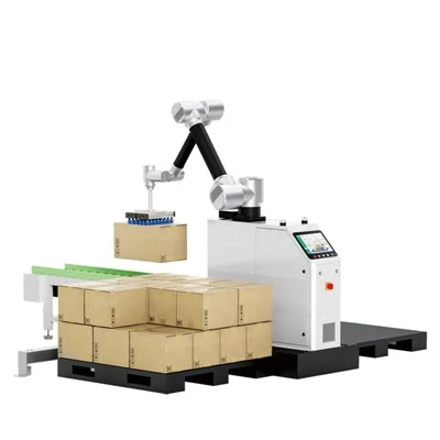
Whether you’re automating packaging, electronics assembly, logistics, or food processing, the right vision system can make the difference between a robot that’s a costly liability and one that pays for itself in a matter of months. If you’re considering integrating a pick and place robot into your operation, the first step isn’t looking for the cheapest option—it’s talking through your specific needs. Our team works with every client to assess their conveyor speeds, part sizes, environments, and quality requirements to design a vision system that fits, not one that’s one-size-fits-all. To learn more about how we can customize a pick and place robot with the right vision system for your business, reach out to our team to schedule a consultation. We’ll walk you through the options, address your concerns, and build a solution that works for your unique operations.
Palletizing Robot References
- Machine Vision for Industrial Automation, AIA (Automation Industry Association), 2022.
- “3D Vision Technologies for Robotic Pick-and-Place Applications”, IEEE Transactions on Robotics, Vol. 38, No. 4, 2022.
- LED Lighting Solutions for Industrial Vision Systems, International Society of Automation (ISA), 2021.
- Pick-and-Place Robot Calibration Best Practices, Robotics Industries Association (RIA), 2020.
Robotic Technology (GD) Co., Ltd.
Robotic Technology (GD) Co., Ltd. is one of the most experienced pick and place robot manufacturers and suppliers in China, also supports custom service and one year warranty. Please feel free to wholesale CE approved pick and place robot for sale here from our factory. Contact us for quotation.
Address: Room 102, No. 30,Hengfeng 2nd Road,Daguo, Changping Town, Dongguan City,Guangdong,China
E-mail: admin@iroboticplus.com
WebSite: https://www.rb-tic.com/
